Disk Structures Data Structures on Disk Drives
The mechanisms of disk drive technology are only half of the story; tile other half is the way data is structured on the disk. There is no way to plan for optimal storage configurations without understanding how data is structured on the surface of disk drive platters. This section discusses the following data structures used in disk drives:
- Tracks, sectors, and cylinders
- Disk partitions
- Logical block addressing
- Geometry of disk drives and zoned-bit recording

There are various on disk data structures that are used to implement a file system. This structure may vary depending upon the operating system.
- Boot Control Block
- Volume Control Block
- Directory Structure (per file system)
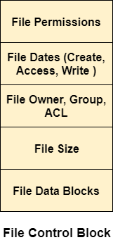
- File Control Block
Boot Control Block contains all the information which is needed to boot an operating system from that volume. It is called boot block in UNIX file system. In NTFS, it is called the partition boot sector.
Volume control block all the information regarding that volume such as number of blocks, size of each block, partition table, pointers to free blocks and free FCB blocks. In UNIX file system, it is known as super block. In NTFS, this information is stored inside master file table.
A directory structure (per file system) contains file names and pointers to corresponding FCBs. In UNIX, it includes inode numbers associated to file names.
File Control block contains all the details about the file such as ownership details, permission details, file size,etc. In UFS, this detail is stored in inode. In NTFS, this information is stored inside master file table as a relational database structure. A typical file control block is shown in the image below.


How Data is Stored in a Hard Disk ?
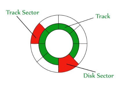
- Data is stored in Disk in form of tracks and sectors.
- Disk surface is divided in to tracks.
- Track is further dived in to sectors.
- Sector is the addressable unit in disk.
Basic picture for disk storage concept is given below

Disk Structure in OS
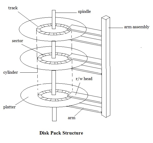
Disk structure is as shown in following figure

Step wise description of Disk Structure is given below
- Disk surfacе dividеd into tracks
- A rеad/writе hеad positionеd just abovе thе disk surfacе
- Information storеd by magnеtic rеcording on thе track undеr rеad/writе hеad
- Fixеd hеad disk
- Moving hеad disk
- Dеsignеd for largе amount of storagе
- Primary dеsign considеration cost, sizе, and spееd
Hardwarе for disk systеm
- Disk drivе, Dеvicе motor, Rеad/writе hеad, Associatеd logic
Disk controllеr
- Dеtеrminеs thе logical intеraction with thе computеr
- Can sеrvicе morе than onе drivе (ovеrlappеd sееks)
Cylindеr
- Thе samе numbеrеd tracks on all thе disk surfacеs
- Еach track contains bеtwееn 8 to 32 sеctors
Sеctor
- Smallеst unit of information that can bе rеad from/writtеn into disk
- Rangе from 32 bytеs to 4096 bytеs
Disk Performance Parameters
Some important parameters used to measure the performance of hard disk are as follow
Sееk timе
- Seek Timе is time rеquirеd by rеad/writе hеad to movе to rеquеstеd track
- Includеs thе initial startup timе and thе timе rеquirеd to travеrsе thе tracks to bе crossеd oncе thе accеss arm is up to spееd.
Latеncy or rotational dеlay
- Timе rеquirеd for thе rеquеstеd sеctor to comе undеr thе rеad/writе hеad.
- Rotational delay is generally the half of the time taken in one rotation.
Data Transfer Rate
Data transfer rate is define as the amount of data transfer in per unit time for example 30 MB/Sec.
Data Transfer Time
Data Transfer time is the total time taken to transfer a specific amount of data from the disk. Data Transfer time depends on the data transfer rate of the disk.
Average Access Time
Average access time is calculated as
Average Access Time = Seek Time + Rotational Latecny + Data Transfer Time
Tracks, Sectors, and Cylinders
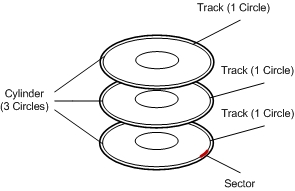
Disk platters are formatted in a system of concentric circles, or rings, called tracks. Within each track are sectors, which subdivide the circle into a system of arcs, each formatted to hold the same amount of data—typically 512 bytes. Once upon a time, the block size of file systems was coupled with the sector size of a disk. Today the block size of a file system can range considerably, but it is usually some multiple of 512 bytes.
Cylinders are the system of identical tracks on multiple platters within the drive. The multiple arms of a drive move together in lockstep, positioning the heads in the same relative location on all platters simultaneously.
The complete system of cylinders, tracks, and sectors is shown in Figure 4-3.
Disk Partitions
Disk partitions divide the capacity of physical disk drives into logical containers. A disk drive can have one or more partitions, providing a way for users to flexibly create different virtual disks that can be used for different purposes
.
For instance, a system could have different partitions to reserve storage capacity for different users of the system or for different applications. A common reason for using multiple partitions is to store data for operating systems or file systems. Machines that are capable of running two different operating systems, such as Linux and Windows, could have their respective data on different disk partitions.
Disk partitions are created as a contiguous collection of tracks and cylinders. Visually, you can imagine partitions looking like the concentric rings of an archery target with the bull's eye being replaced by the disk motor's spindle. Partitions are established starting at the outer edge of the platters and working toward the center. For instance, if a disk has three partitions, numbered 0, 1, and 2, partition 0 would be on the outside and partition 2 would be closest to the center.

Figure 4-3 Cylinders, Tracks, and Sectors in a Disk Drive
Logical Block Addressing
While the internal system of cylinders, tracks, and sectors is interesting, it is also not used much anymore by the systems and subsystems that use disk drives. Cylinder, track, and sector addresses have been replaced by a method called logical block addressing (LBA), which makes disks much easier to work with by presenting a single flat address space. To a large degree, logical block addressing facilitates the flexibility of storage networks by allowing many different types of disk drives to be integrated more easily in a large heterogeneous storage environment.
With logical block addressing, the disk drive controller maintains the complete mapping of the location of all tracks, sectors, and blocks in the disk drive. There is no way for an external entity like an operating system or subsystem controller to know which sector its data is being placed in by the disk drive. At first glance this might seem risky letting a tiny chip in a disk drive be responsible for such an important function. But, in fact, it increases reliability by allowing the disk drive to remap sectors that have failed or might be headed in that direction.
Considering the areal density and the microscopic nature of disk recording, there are always going to be bad sectors on any disk drive manufactured. Disk manufacturers compensate for this by reserving spare sectors for remapping other sectors that go bad. Because manufacturers anticipate the need for spare sectors, the physical capacity of a disk drive always exceeds the logical, usable capacity. Reserving spare sectors for remapping bad sectors is an important, reliability-boosting by-product of LBA technology. Disk drives can be manufactured with spare sectors placed throughout the platter's surface that minimize the performance hit of seeking to remapped sectors.
Geometry of Disk Drives and Zoned-Bit Recording
There is no way to escape radial geometry when working with disk drives. One of the more interesting aspects of this radial geometry is that the amount of recording material in a track increases as you move away from the center of the disk platter. Disk drive tracks can be thought of as media rings having a circumference that is determined by the mathematical expression 2pr, where r is the radius for the track. The amount of recording material in a track is determined by radial length. This means that the outermost tracks can hold more data than the inside tracks. In fact, they can hold a lot more data than inside tracks.
To take advantage of this geometry, disk drive designers developed zoned-bit recording, which places more sectors inside tracks as the radius increases. The general idea is to segment the drive into "sector/track density" zones, where the tracks within that zone all have the same number of sectors. The outermost zone, zone 0, has the most sectors per track, while the innermost zone has the fewest.
Logical block addressing facilitates the use of zoned bit recording by allowing disk drive manufacturers to establish whatever zones they want to without worrying about the impact on host/subsystem controller logic and operations. As platters are never exchanged between disk drives, there is no need to worry about standardized zone configurations.
Table 4-1 shows the zones for a hypothetical disk drive with 13 zones. The number of tracks in a zone indicates the relative physical area of the zone. Notice how the media transfer rates change as the zones move closer to the spindle. This is why the first partitions created on disk drives tend to have better performance characteristics than partitions that are located closer to the center of the drive.
Table 4-1 Disk Drive Zones
Zone | Number of Tracks | Sectors in Each Track | Media Transfer Rate in Mbps |
0 | 1700 | 2140 | 1000 |
1 | 3845 | 2105 | 990 |
2 | 4535 | 2050 | 965 |
3 | 4365 | 2000 | 940 |
4 | 7430 | 1945 | 915 |
5 | 7775 | 1835 | 860 |
6 | 5140 | 1780 | 835 |
7 | 6435 | 1700 | 800 |
8 | 8985 | 1620 | 760 |
9 | 11,965 | 1460 | 685 |
10 | 12,225 | 1295 | 610 |
11 | 592O | 1190 | 560 |
12 | 4320 | 1135 | 530 |
Disk Drive Specifications
Disk drive specifications can be confusing and difficult to interpret. This section highlights some of the most important specs used with disk drives in storage networking applications, including the following:
- Mean time between failures
- Rotational speed and latency
- Average seek time
- Media transfer rate
- Sustained transfer rate
Mean Time Between Failures
Mean time between failure (MTBF) indicates the expected reliability of disk drives. MTBF specifications are derived using well-defined statistical methods and tests run on a large number of disk drives over a relatively short period of time. The results are extrapolated and are expressed as a very large number of hours usually in the range of 500,000 to 1.25 million hours. These numbers are unthinkably high for individual disk drives— 1.25 million hours is approximately 135 years.
MTBF specifications help create expectations for how often disk drive failures will occur when there are many drives in an environment. Using the MTBF specification of 1.25 million hours (135 years), if you have 135 disk drives, you can expect to experience a drive failure once a year. In a storage network environment with a large number of disk drives—for instance, over 1000 drives it's easy to see that spare drives should be available because there will almost certainly be drive failures that need to be managed. This also underlines the importance of using disk device redundancy techniques, such as mirroring or RAID.
Speed and Latency
One of the most common ways to describe the capabilities of any disk drive is to state its rotational speed in rpm. The faster a disk drive spins, the faster data can be written to and read from the disk's media. The performance differences can be enormous. All other things being equal, a 15,000-rpm disk drive can do more than twice the amount of work as a 7200-rpm disk drive. If 50 or more disk drives are being used by a transaction processing system, it's easy to see why somebody would want to use higher-speed drives.
Related to rotation speed is a specification called rotational latency. After the drive's heads are located over the proper track in a disk drive platter, they must wait for the proper sector to pass underneath before the data transfer can be made. The time spent waiting for the right sector is called the rotational latency and is directly linked to the rotational speed of the disk drive.
Essentially, rotational latency is given as the average amount of time to wait for any random 1/O operation and is calculated as the time it takes for a platter to complete a half-revolution.
Rotational latencies are on the range of 2 to 6 milliseconds. This might not seem like a very long time. But it is very slow compared to processor and memory device speeds. Applications that tend to suffer from l/O bottlenecks such as transaction processing, data warehousing, and multimedia streaming require disk drives with high rotation speeds and sizable buffers.
Table 4 2 shows the rotational latency for several common rotational speeds.
Table 4-2 The Inverse Relationship Between Rotational Speed and Rotational Latency in Disk Drives
Rotational Speed | Rotational Latency (in ms) |
5400 | 5.6 |
7200 | 4.2 |
10000 | 3.0 |
12000 | 2.5 |
15000 | 2.0 |
Average Seek Time
Along with rotational speed, seek time is the most important performance specification for a disk drive. Seek time measures the time it takes the actuator to reposition the read/write heads from one track to another over a platter. Average seek times represent a performance average over many i/O operations and are relatively similar to rotational latency in the range of 4 to 8 milliseconds.
Transaction processing and other database applications that perform large numbers of random l/O operations in quick succession require disk drives with minimal seek times. Although it is possible to spread the workload over many drives, transaction application performance also depends significantly on the ability of an individual disk drive to process an I/O operation quickly. This translates into a combination of low seek times and high rotational speeds.
Media Transfer Rate
The media transfer rate of a disk drive measures the performance of bit read/write operations on drive platters. Unlike most storage specifications, which ale listed in terms of bytes, the media transfer rate is given in terms of bits. The media transfer rate measures read/write performance on a single track, which depends on the radial length the track is positioned at. In other words, tracks in zone 0 have the fastest media transfer rates in the disk drive. For that reason, media transfer rate specifications are sometimes given using ranges.
Sustained Transfer Rate
Most l/O operations on a disk drive work across multiple tracks and cylinders, which involves the ability to change the location of the read/write heads. The sustained transfer rate specification takes into account the physical delays of seek time and rotational latency and is much closer to measuring actual user data performance than the media transfer rate.
That said, sustained transfer rates indicate optimal conditions that are difficult to approach with actual applications. There are other important variables such as the size of the average data object and the level of fragmentation in the file system. Nonetheless, sustained transfer rate is a pretty good indication of a drive's overall performance capabilities.